
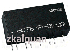



ISO D-P-O-Q: Isolation Transmitter IC for DA Conversion of PWM Pulse Width Signals
Single-Chip Microcomputer PWM to 4-20mA / 0–10V Analog Signal Isolation Transmitter
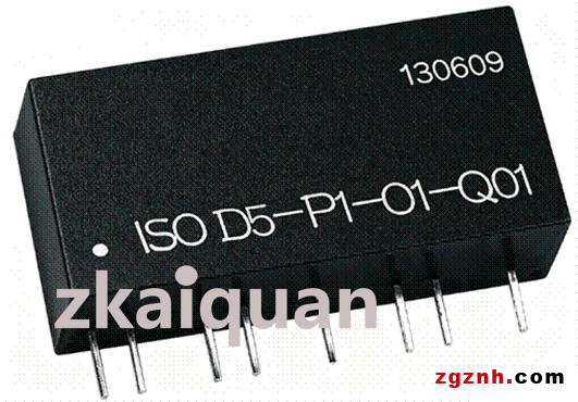
Prices in the link are for reference only. Contact the staff at the end of the article for exact pricing.
We accept OEM customization as well as ODM development, design and manufacturing services.
Product Features:
● High resolution and fast response speed for PWM to 4-20mA / 0-10V analog signal conversion
● Excellent linearity across the full measurement range (non-linearity < 0.2%)
● 3000 VDC triple isolation between auxiliary power supply, signal input and signal output
● Auxiliary power supply: single DC power supply of 5 V, 12 V, 15 V or 24 V
● Low cost & ultra-small size; SIP-12 package with UL94V-0 flame retardant rating
● Strong immunity against EMC electromagnetic interference and high-frequency spatial interference
● Industrial operating temperature range: -40 ℃ ~ +85 ℃
Typical Applications:
● Transmission, isolation and long-distance wiring transmission of PWM signals
● Precision linear control via analog signals converted from PWM signals
● Conversion of MCU PWM signals into analog signals
● On-site industrial control for PLCs and inverters
● Suppression of ground loop current interference
● Automatic selective temperature control for industrial boilers
● DA converters and transmitters built based on PWM technology
Overview:
The ISO D-P-O-Q series is a newly developed, industry-leading compact-size (SIP12 Pin), low-cost isolated transmitter IC for PWM pulse-width modulation signals launched by Shunyuan. It can convert the duty cycle of PWM square-wave signals output from MCUs, PLC/DCS systems and instruments into standard 4-20mA/0-10V analog signals via galvanic isolation, realizing isolated amplification, display and control of MCU PWM signals.
The ISO D-P-O-Q integrates multiple high-isolation DC/DC power supplies, analog amplification & conversion circuits, and PWM signal isolation control circuits inside a single module. It is perfectly suited for DA reconstruction, isolation and transmission of PWM signals in industrial sites, as well as multi-channel sensor signal collection and analysis by MCUs, field buses, Ethernet IoT devices, PLC/DCS host computers. The built-in high-efficiency isolated DC/DC power supply independently supplies power to the internal output conditioning circuit, DA conversion circuit and output signal isolation circuit. Adopting SMD structure and advanced isolation technology, the component achieves 3000 VDC triple isolation among auxiliary power supply, PWM signal input and analog signal output, and can withstand harsh industrial operating conditions including wide temperature range, high humidity and mechanical vibration.
The ISO D-P-O-Q series boasts user-friendly operation, capable of completing isolation and transmission between PWM signals and analog signals without any external peripheral components. Featuring an ultra-small 12-pin SIP package (33.0×15.5×10.5 mm) and standard PCB mounting design, it greatly simplifies system design and reduces equipment size and wiring costs. Three installation options are available: PCB IC mounting, standard DIN35 rail mounting and PIM panel embedded mounting. The DIN rail version supports isolated signal transmission modes of one-input-one-output and one-input-two-output. The intelligent PIM panel embedded transmitter module realizes multiple functions such as isolated display, alarm control and long-distance lossless transmission of sensor analog signals.
These products are widely applied in metallurgy & mining, petrochemical industry, power equipment, medical instruments, industrial automation, new energy equipment, military industry and scientific research. Users can select suitable models according to actual on-site working requirements.
General Specifications:
Accuracy: 0.5%
Hysteresis: <0.5%
Auxiliary Power Supply: DC 5 V, 12 V, 24 V, tolerance ±5%
Isolation: Between signal input, signal output and auxiliary power supply
Operating Temperature: -40 ℃ ~ +85 ℃
Insulation Resistance: ≥20 MΩ
Operating Humidity: 10% ~ 90% (non-condensing)
Withstand Voltage: 3000 VDC, 50 Hz, 1 minute, leakage current ≤1 mA, isolated among signal input, signal output and auxiliary power supply
Storage Temperature: -55 ℃ ~ +105 ℃
Storage Humidity: 10% ~ 95% (non-condensing)
Impulse Withstand Voltage: 1 kV, 1.2/50 μs (peak value)
Absolute Maximum Ratings:
(Long-term operation under absolute maximum rating conditions will shorten the service life of the product; exceeding the maximum ratings will cause irreversible permanent damage.)
Continuous Isolation Voltage: 3000 VDC/rms
PW (Power Supply Input Voltage Range): ±10% Vdd
Junction Temperature: -40 ℃ ~ +85 ℃
Lead Solder Temperature (Duration < 10 s): 260 ℃
Technical Specifications:
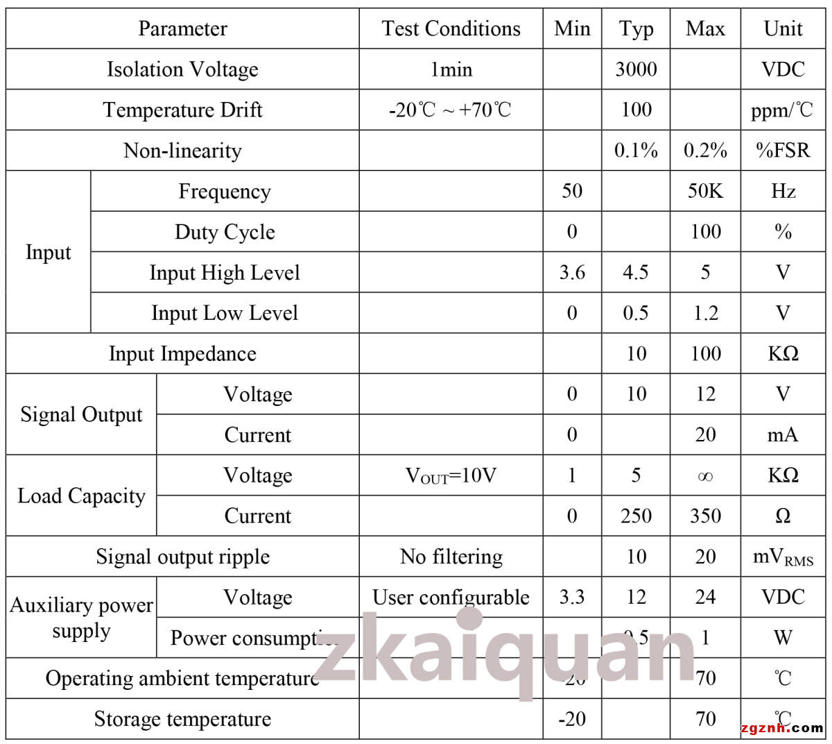
Notes:
▲If users have requirements for the load‑driving capability of the product’s voltage or current signal output, customization is available according to technical specifications.
▲For users selecting IC‑packaged products for PCB mounting: when the amplitude of the field input signal (high‑level) is 24 V, divide the input amplitude down to 5 V before connecting to the product, to prevent abnormal operation or damage to the unit.
▲For users selecting DIN35 or DIN3 rail‑mounted products: if the field input signal amplitude (high‑level) is 24 V, please specially specify the 24 V signal amplitude when placing the order. The voltage‑dividing circuit will be pre‑installed inside the product before delivery.
Model and Definition:
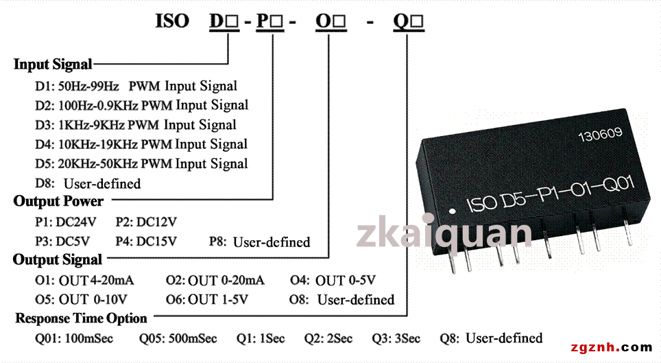
Selection Examples:
Example 1: Signal input: 20 kHz square wave; Signal output: 4‑20 mA; Response time: 100 mSec; Auxiliary power supply: 24 V; Corresponding product model: ISO D5‑P1‑O1‑Q01
Example 2: Signal input: 50 Hz square wave; Signal output: 0‑5 V; Response time: 3 Sec; Auxiliary power supply: 12 V; Corresponding product model: ISO D1‑P2‑O4‑Q3
Typical Applications:
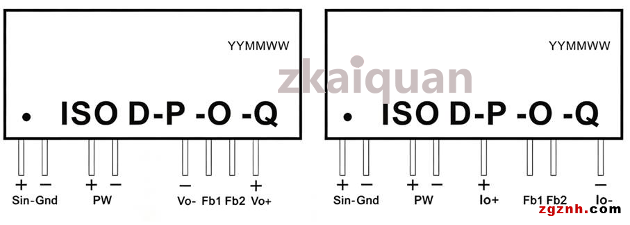
Application 1:
The 4‑20 mA / 0‑10 V analog signals output by sensors and transmitters are isolated and converted into PWM signals via the ISO U‑P‑D‑Q module. The signals are transmitted remotely without distortion through the ISO CAN module, and then restored to 4‑20 mA / 0‑5 V analog signals by the ISO D‑P‑O‑Q module for linear precision control.
Outline Dimensions and Pin Function Description:
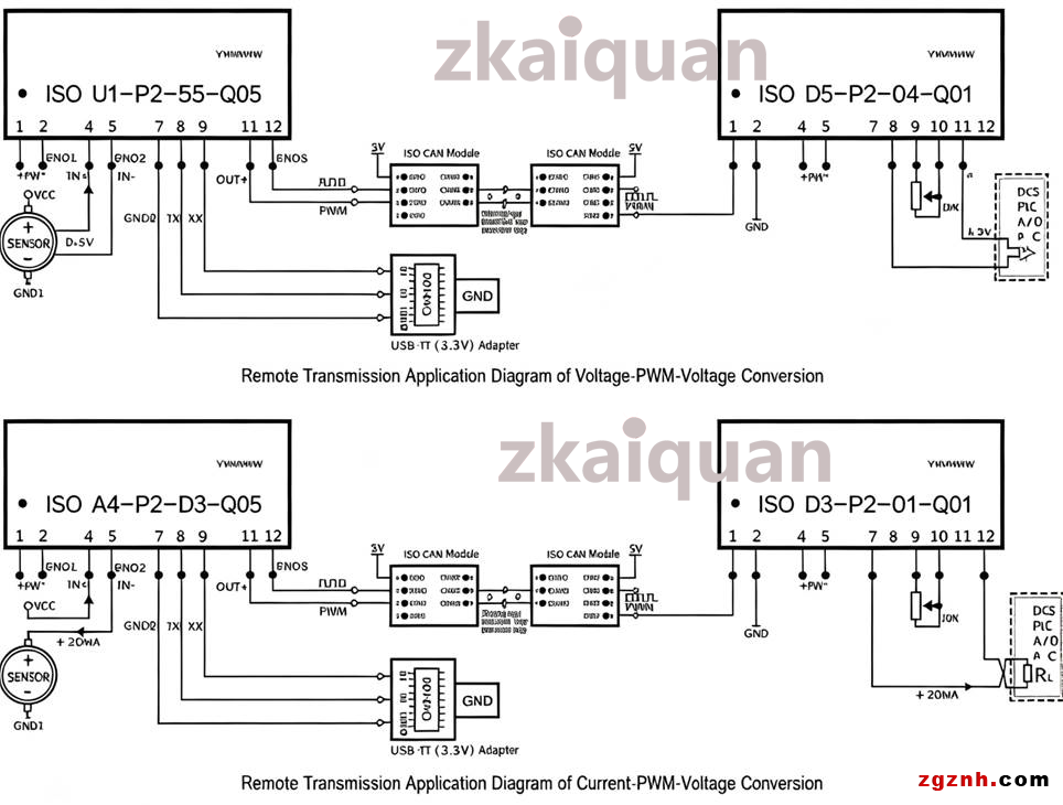
Outline Dimensions and Pin Function Description:
Application 1: The 4-20mA/0-10V analog signals output by sensors and transmitters are isolated and converted into PWM signals via the ISO U-P-D-Q module. The signals are transmitted remotely without distortion through the ISO CAN module, and then restored to 4-20mA/0-5V analog signals by the ISO D-P-O-Q module for linear precision control.
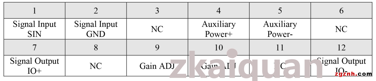
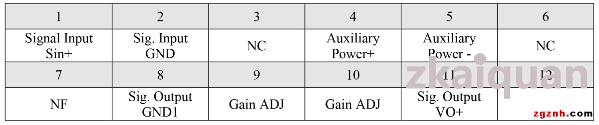
Outline Dimensions and Pin Function Description:
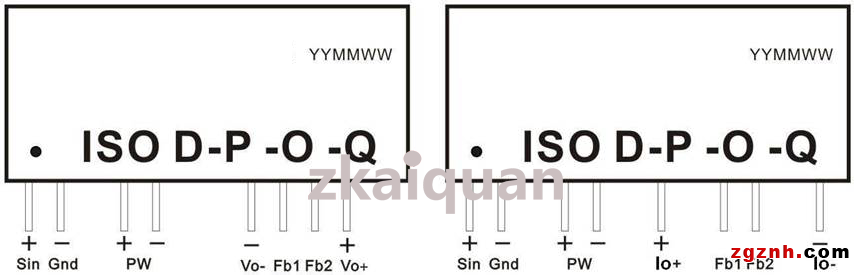
(1) Pin Description of Current Output Type Product: Single In-line Package 12 pins (SIP 12)
(2) Pin Description of Voltage Output Type Product: Single In-line Package 12 pins (SIP 12)
DIN3 Series:
Low-cost, small-size DIN rail mount product outline dimensions and pin function description
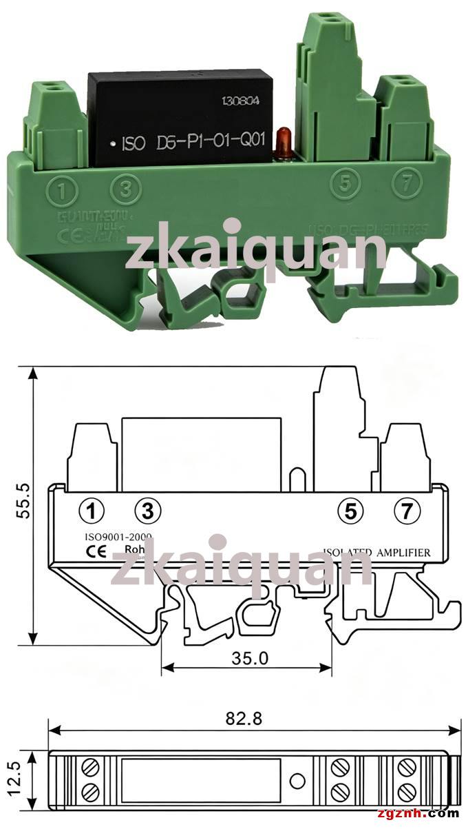
DIN3 Series DIN Rail Mounting: Low-cost Compact Single-channel PWM Signal Isolation Amplifier Transmitter Pin Description:

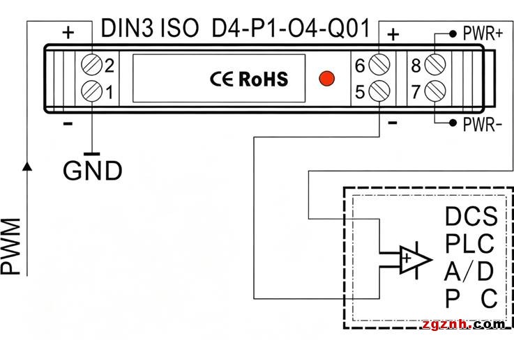
DIN3 Series – Compact DIN Rail Mount Typical Application Wiring Diagram:
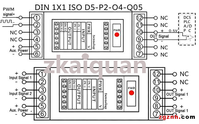
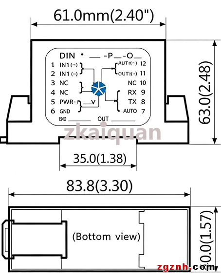
DIN35 Series, Single-channel DIN 1X1, Dual-channel DIN 2X2 DIN Rail Mount PWM Transmitter – Outline Dimensions and Pin Function Description:
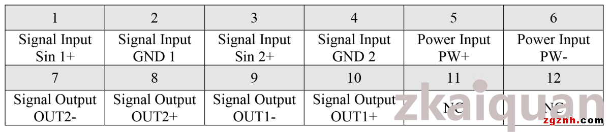
Pin Description for DIN 1×1 / 2×2 DIN Rail Mount PWM Signal Isolation Amplifier Transmitter:
Typical Application:
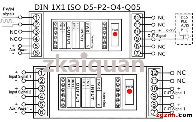
The 4-20mA/0-10V analog signals output by sensors and transmitters are isolated and converted into PWM signals via the DIN1X1 ISO U-P-D-Q module. The signals are transmitted remotely without distortion through the ISOCAN module, and then restored to 4-20mA/0-5V analog signals by the DIN1X1 ISO D-P-O-Q module for linear precision control.
Introduction to PIM Series Panel-mount Intelligent PWM Signal Transmitter with Display & Control Function:
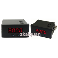
PIM-ISO D-P-O-Q-LED7 Series Panel Embedded Analog Isolation Transmitter Meter, Adopting intelligent design, the PIM-ISO D-P-O-Q-LED7 series panel embedded analog isolation transmitter meter integrates multiple functions unavailable in conventional products. The intelligent transmitter meter converts standard analog signals into PWM outputs with a duty cycle ranging from 0% to 100%, and linearly displays the analog signals in decimal digital values corresponding to the configured range.
This embedded intelligent digital display meter is operated via two combined keys and controlled by a CPU. It supports configuration of multiple parameters including zero point, full scale, decimal point, alarm and delay, delivering great flexibility and practicality. Two multi-functional circuit boards (basic function board and extended function board) are embedded inside the device. Developed mainly for DC motor speed regulation, stepper motor speed control and industrial site lighting dimming, the meter outputs 0%–100% PWM signals after power-up. Meanwhile, it can display real-time motor speed or lighting brightness for intuitive operation. Equipped with an onboard communication interface, the meter can connect to a PC via a USB cable. Users can link the communication interface to their industrial system configuration network to realize intelligent data management.
Benefiting from integrated manufacturing processes and innovative isolation technologies, the module achieves an isolation voltage of 2500 VAC and meets industrial requirements for harsh operating environments with wide temperature ranges, humidity and vibration. As a new-generation low-cost, compact and multi-functional intelligent isolation transmitter instrument, it realizes industrial signal conversion, anti-interference isolation, display and control. It is widely applied in motor speed regulation, lighting dimming, metallurgy & mining, petrochemical industry, power equipment, medical instruments, industrial automation, new energy facilities, military research and other fields.
The PIM-ISO D-P-O-Q-LED7 is primarily used for isolation transmission, display and control of analog voltage and current signals, with prominent applications in motor speed control and lighting adjustment. The embedded digital meter measures input voltage and current signals. Thanks to the linear signal correspondence, it can indirectly display monitored physical quantities such as motor speed, lighting brightness, liquid flow rate and PWM duty cycle, and supports alarm output control.
The numerical value displayed by the intelligent digital meter is not the raw measured signal value, but a scaled reading between two preset values. The measured zero and full-scale signals are mapped linearly to the two preset values for display.
Example 1: For a 4–20 mA input signal, set 4 mA = 0 and 20 mA = 8000. The display reads 2000 at 8 mA input and 4000 at 12 mA input.
Example 2: Set 4 mA = 1000 and 20 mA = -1000. The display reads 0 at 12 mA input and -500 at 16 mA input.
The digital display range is from -1999 to 9999 (4-digit display). The device features an alarm function with two isolated switch outputs for local display, control and alarm. The two alarm setpoints support forward and reverse alarm direction configuration. Alarms are triggered based on the displayed reading. When an alarm activates, the decimal point on the last digit of the LED panel flashes, and the alarm signal is output through digital optocoupler isolation. For units requiring alarm functions, the upper/lower alarm threshold and alarm mode can be modified via a programmer. Refer to the Transmitter Meter Software Configuration Guide on the subsequent page for detailed setup procedures.
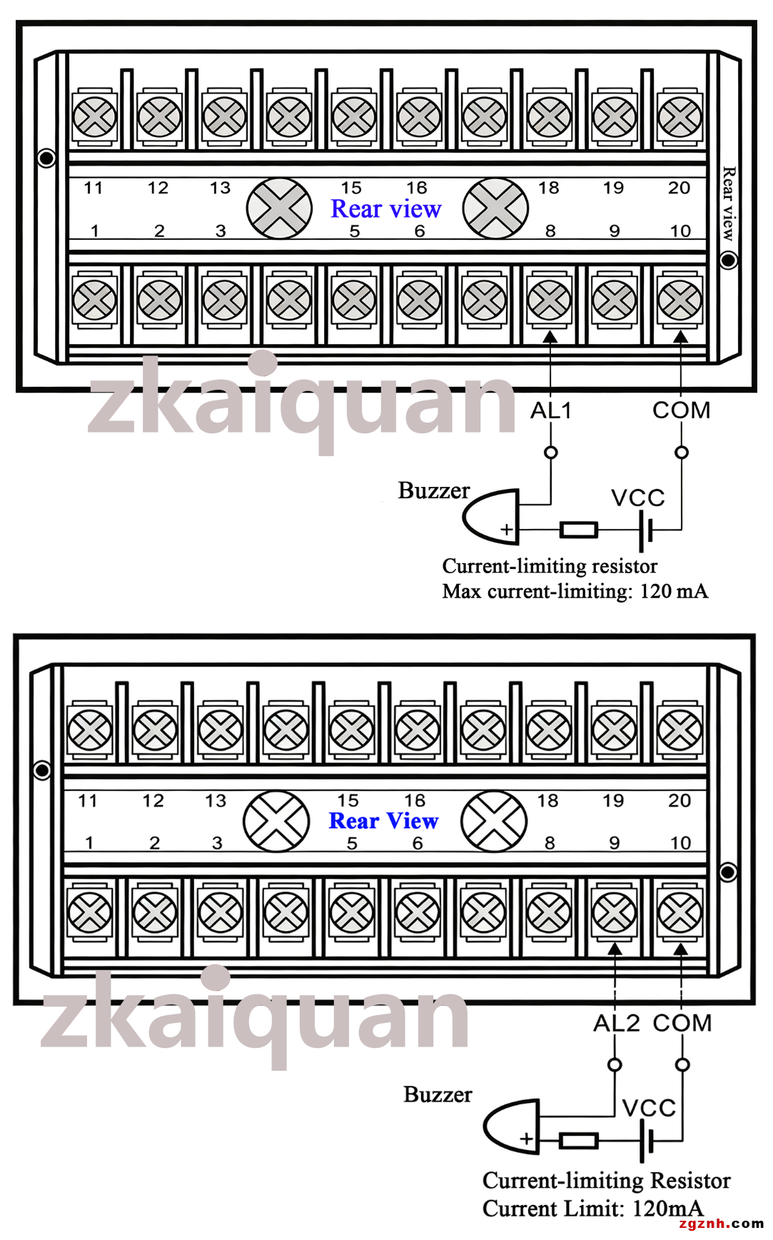
Note: The alarm signal is open-collector (OC) output. Refer to the section [Alarm Output and Application] on the following page for specific wiring and application methods.
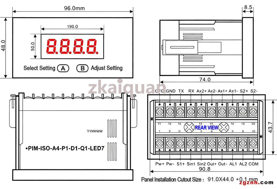
Outline Dimensions:
The PIM LED7 series panel embedded intelligent transmitter meter adopts a flame-retardant plastic housing.
Outline dimensions: 96×48×74 mm
Panel cutout size: 91.0×44.0 (+0.1) mm
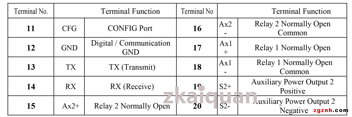
Terminal Function Description:
Two layers of multi-functional circuit boards (basic function board and extension function board) are embedded inside the instrument.
(Pins for unselected options during ordering are NC. Please refer to the rear view of the instrument below.)
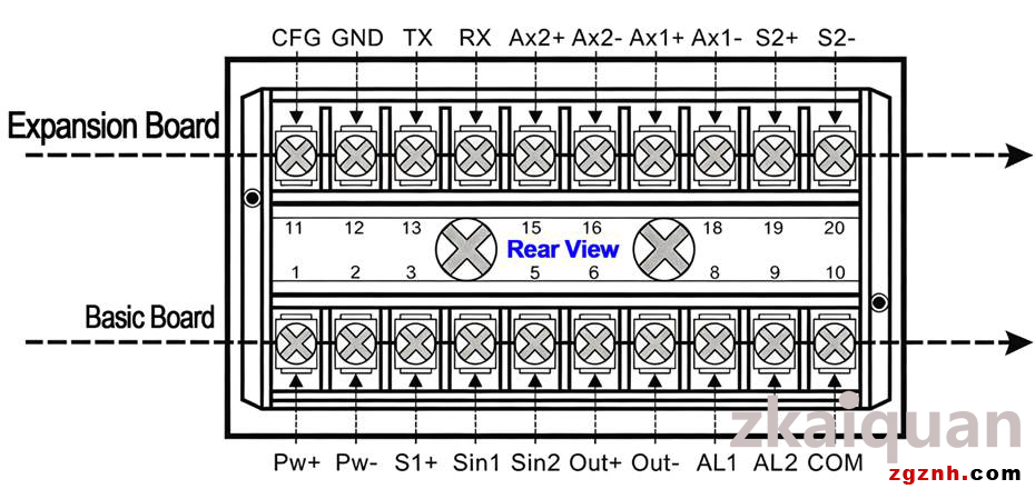
Layer 1 – Basic Function Board:
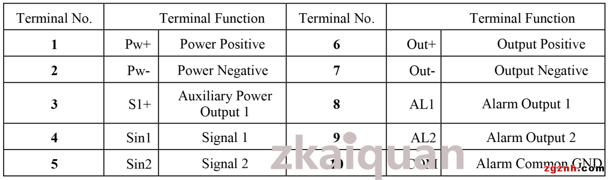
Layer 2: Extension Function Board:(Note: Extended functions of the instrument can be customized according to customer requirements.)
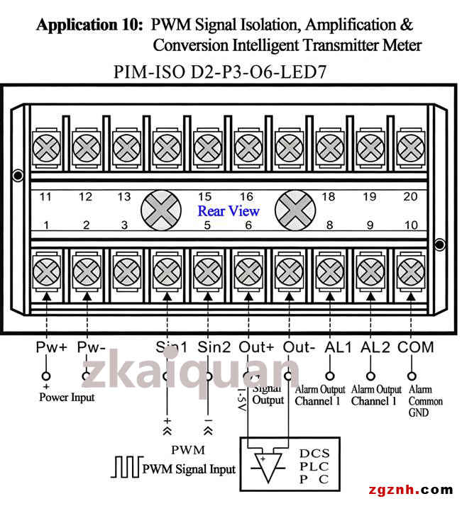
Typical Application Wiring Diagram:
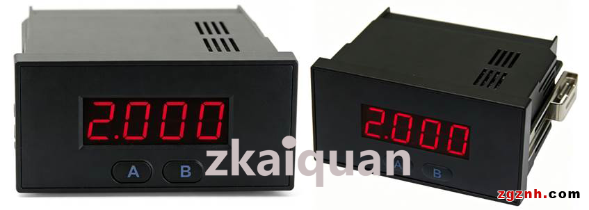
Product Photos of PIM Panel-mount Instrument:
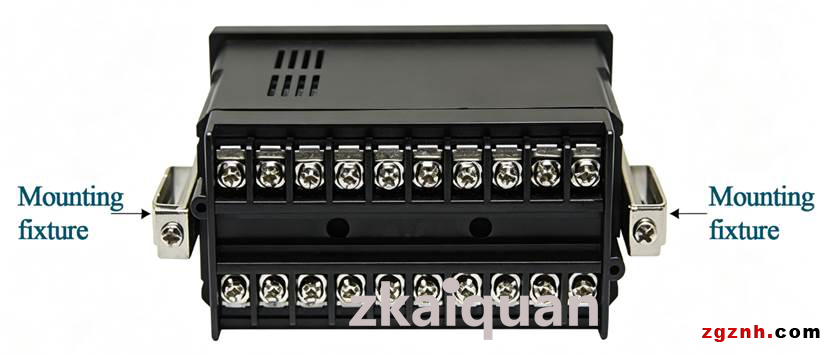
Installation Instructions:
Drill the cutout according to the product cutout size. Insert the front side of the instrument into the cutout, then secure the product to the opening with mounting fixtures from the rear side.
The mounting fixture is equipped with one screw. Tighten the screw with a screwdriver to complete installation.
Alarm Output and Application:
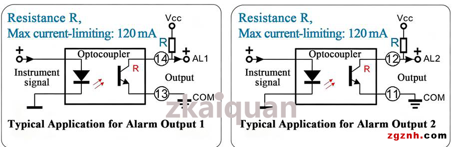
•The two alarm signals of the PIM LED7 series analog intelligent transmitter meter are DC level signals generated by the internal microprocessor chip. After optocoupler isolation, a low output level indicates an alarm state, and a high output level indicates a non-alarm state.
•Due to the limited drive current of the internal microprocessor I/O ports, the alarm signal is very weak, with a minimum value of only 0.5 mA. Signals from the I/O ports are isolated by phototransistor-type optocouplers with strong current expansion capability, adopting open-collector (OC) output. When an external pull-up voltage is connected to the output, the maximum current can be expanded to 120 mA.
The working principle of this phototransistor optocoupler is shown in the figure below. After the instrument signal passes through optocoupler isolation:
Terminals AL1 and AL2 are the collector positive outputs of the optocoupler OC signals, and COM is the output common ground. Connect COM to an external power supply circuit of the instrument to further amplify and boost the alarm signal. The signal can finally drive required actuators such as buzzers, indicator lights, relays, cooling and heating equipment, motors, etc.
AL1 stands for Channel 1 Alarm Output, AL2 stands for Channel 2 Alarm Output. The two alarm channels share the common ground COM.
•Restricted by the maximum collector current Ic of the phototransistor, its current expansion and load driving capacity are limited. If users require higher driving current for on-site devices such as relays, solenoid valves and stepper motors, an external power expansion circuit (power amplifier transistor or servo circuit) can be adopted for current amplification, or special customization can be requested.
Precautions for Selection of Intelligent Transmitter Meter:
Please read the entire manual carefully before ordering to confirm whether this product meets your requirements and ensure proper model selection.
•The product is delivered without alarm function by factory default, with a default display range of 0.0–200.0.
•Customers are recommended to specify display specifications when placing the initial order. Our company can complete parameter configuration before delivery. Please contact us promptly if you have any questions.
•Do not reverse the wiring of input signal and power supply; otherwise, the intelligent transmitter meter may be damaged.
•Do not use the product in humid environments or environments with corrosive gas, otherwise the service life will be shortened or the unit may be permanently damaged.
Software Configuration Guide for PIM LED7 Series Analog Intelligent Transmitter Meter:
The input/output signals of the PIM LED7 series analog intelligent transmitter meter have a linear correspondence with the panel display values.
Example 1: For an input signal of 0~10V, the panel displays 0~1000. The mapping is 0V → 0, 5V → 500, 10V → 1000.
Example 2: For an input signal of 4~20mA, the panel displays 40~200. The mapping is 4mA → 40, 12mA → 120, 20mA → 200.
The display range of the digital meter is -1999 ~ 9999. Users can set and save parameters including zero point value, full scale value, two alarm setpoints and decimal point via the two buttons A/B on the transmitter front panel.
The PIM LED7 series analog intelligent transmitter meter is equipped with two isolated switch outputs for local display, control and alarm, and supports forward/reverse alarm direction configuration. Alarms are triggered based on the displayed reading. When an alarm occurs, the decimal point of the last digit on the LED panel flashes.
1. Parameter Configuration Instructions
After the input signal is connected to the instrument, the unit powers on and performs self-test. The startup logo screen will appear, and then the unit enters the measurement display mode.
① Zero Point Setting
Press A+B to call up the zero point setting screen . Press A+B again to enter zero point configuration; the screen displays the current set value
  , with the last digit blinking. Press key A to toggle the blinking position among the four digital tubes (the blinking digit is adjustable). Press key B to cycle the value of the blinking digit from 0 to 9 (the leftmost digit cycles among “–, -1, 0 ~ 9”). Adjust each digit according to the required reading. After configuration, press A+B to confirm and return to the screen .
② Full Scale Setting
Press key A to enter the full scale setting screen . Press A+B to access full scale configuration, and the screen shows the current set value
  . All operation steps are the same as item ①. After configuration, press A+B to confirm and return to the screen
  .
.
③ Decimal Point Setting
Press key A to enter the decimal point setting screen  . Press A+B to open the current value screen
  . Press key B to shift the decimal point one position to the left
  ; keep pressing B to cycle the decimal point position leftwards.
After configuration, press A+B to confirm and return to the screen  .
.
④ Damping Time
Press key A to enter the damping time setting screen  . Press A+B to open the current value screen
  . Damping time can be set from 0 s to 20 s. Press A to decrease the value; press B to increase the value. Values change in increments of 0.5 s. After configuration, press A+B to confirm and return to the screen .
⑤ Alarm Enable Setting
Press key A to enter the alarm enable setting screen  . Press A+B to open alarm enable configuration, and the displayed value
 indicates that subsequent alarm parameters will not take effect. Press A or B to switch to status
  , which means all subsequent alarm settings will be activated. Regardless of alarm conditions, the last decimal point on the LED panel will flash as alarm indication. After configuration, press A+B to confirm and return to the menu. Factory default setting is .
⑥ 1st Alarm Setpoint Setting
Press key A to enter the 1st alarm setpoint screen  . Press A+B to open the current value of the 1st alarm setpoint
  . The last digit starts blinking.
Press key A to switch the blinking digit among four positions; press key B to cycle the digit value from 0 to 9 (the leftmost digit cycles among “–, -1, 0 ~ 9”). Set the alarm threshold as required. After configuration, press A+B to confirm and return to the screen .
.
⑦ 2nd Alarm Setpoint Setting
Press key A to enter the 2nd alarm setpoint screen  . The configuration procedure is identical to item ⑥. After configuration, press A+B to confirm and return to the menu.
⑧ 1st Alarm Direction Setting
Press key A to enter the 1st alarm direction setting screen  . Press A+B to view the current setting
  . This status means the alarm triggers when the reading rises upward across the threshold. For example: if the alarm threshold is set to 1000, the alarm activates when the LED reading exceeds 1000 and clears when the reading drops below 1000. Press key B to switch to status
  , which triggers the alarm when the reading falls downward across the threshold. For example: with threshold 1000, the alarm activates when the reading is lower than 1000 and clears when the reading rises above 1000. The alarm will be cleared automatically once the reading returns to the non-alarm range. After configuration, press A+B to confirm and return to the menu.
⑨ 2nd Alarm Direction Setting
Press key A to enter the 2nd alarm direction setting screen  . Adjustment steps are the same as item ⑧.After configuration, press A+B to confirm and return to the menu.
⑩ Alarm Delay Time Setting
Press key A to enter the alarm delay time setting screen  . Press A+B to display the current set value
  . Alarm delay time can be configured from 0 s to 30 s. Press A to increase the value; press B to decrease the value. Values change in increments of 1 second. After configuration, press A+B to confirm and return to the menu.
(Note: Setting value = 0 means no delay. If delay is enabled, the alarm will not activate immediately when alarm conditions are met; the reading must continuously satisfy alarm criteria for the set duration before triggering the alarm. once the reading returns to non-alarm level, the alarm will clear without delay.)
Keep pressing key A to return to the measurement display screen, and all parameter settings are completed.
2. Zero and Full Scale Calibration (Proceed with caution when accessing this menu)
Apply the zero signal to the instrument input. Press and hold key A until the digital meter displays  , then release the key. After 3 seconds, press key A again; the meter shows
  . At this point, the sampled zero input signal is saved as the reference standard. Switch the input signal to the full-scale value. Press key A, the meter displays
  . After 3 seconds, press key A once more; the meter shows
  . The sampled full-scale input signal is now saved as the reference standard. Press key A again to return to measurement mode.
(Note: The zero and full scale values are determined by the input signal range of the meter.
For example, for a 0~10V input signal, zero = 0V and full scale = 10V.
For a 0~±200mV input signal, zero = -200mV and full scale = 200mV.
The same logic applies to all other input signal ranges.)
Precautions for Product Use:
▲ Please read the manual carefully before use. Contact our technical support if you have any questions.
▲ Do not install the product in hazardous areas.
▲ Unauthorized disassembly and assembly of the product is prohibited to avoid equipment failure or malfunction.
After-sales Service:
▲ All products undergo strict inspection and quality control before delivery. If abnormal operation occurs or internal module failure is suspected, please contact our technical support.
▲ The product comes with a 2-year warranty starting from the date of shipment. During the warranty period, any quality defects arising from normal use will be repaired or replaced free of charge by our company.
Notes:
▲ Unless otherwise specified, all data in this document are measured under conditions: Ta=25℃, humidity <75%, nominal input value and rated output load.
▲ All test methods for specifications stated herein comply with our corporate standards.
▲ The above parameters apply only to standard product models listed in this manual. Some specifications of non-standard customized models may exceed the above requirements. Please contact our technical staff for details.
▲ Customization services are available for customers. Specifications are subject to change without prior notice.
Shenzhen Zhikongquan Technology Co., Ltd.:Drawing on 28 years of profound industry experience and accumulated resources, we focus on sectors including industrial automation, sensors, industrial instruments, and robotics. We have integrated manufacturing resources from over a thousand manufacturers. We are committed to promoting Made in China and Created in China to the world, delivering high-quality, cost-effective Chinese products to manufacturing enterprises across the globe. only a selection of our products is listed on our catalog; feel free to contact us for more product information anytime.
Address: Room 1501, Global Logistics Center, No.1 Huanan Avenue, Pinghu Sub-district, Longgang District, Shenzhen City, Guangdong Province, P.R.China
Contact Person: Mulan.Liu
Title: Operations Director
Email: info@zgznh.com
sales1@zgznh.com
https://www.zgznh.com/mall/list-1505.html
WeChat: 13302910296
 粤公网安备44030702001206号