
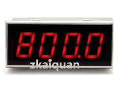



SY LED2-485:2-Wire Passive Intelligent Loop Current LED Digital Display Meter with Communication
Programmable 4-20mA Loop 4-Digit LED Digital Display Meter, 2-Wire Passive Type with Communication Function
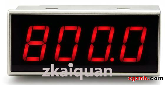
Prices in the link are for reference only. Contact the staff at the end of the article for exact pricing.
We accept OEM customization as well as ODM development, design and manufacturing services.
Product Features:
● Low-cost modular design, supporting embedded installation inside transmitters and various instruments & equipment.
● Adopts 2-wire passive operation mode, no additional auxiliary power supply required.
● RS-485 communication is supported; remote connection to PLC/HMI is available for reading display values and parameter configuration.
● High measuring precision with 4-digit display, accuracy tolerance of ±2 digits.
● Equipped with LED display panel, suitable for both bright and dark environments.
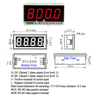
● Compact structure: overall dimension 61.4×26.0 mm, thickness 17.7 mm.
● Industrial-grade operating temperature range: -40℃ ~ +85℃, featuring high reliability.
Typical Applications:
● Indication and control for 4–20mA loops of instruments and sensors
● Operating status display for sensors and transmitters
● Measurement, monitoring and remote control of industrial equipment
● Monitoring of control points in petroleum, chemical, environmental protection and mining systems
● Monitoring and display of temperature, pressure, flow and liquid level signals
● Collection and display of operating data for PLC and DCS systems
● Product development of instruments, medical facilities and industrial control equipment
Overview:
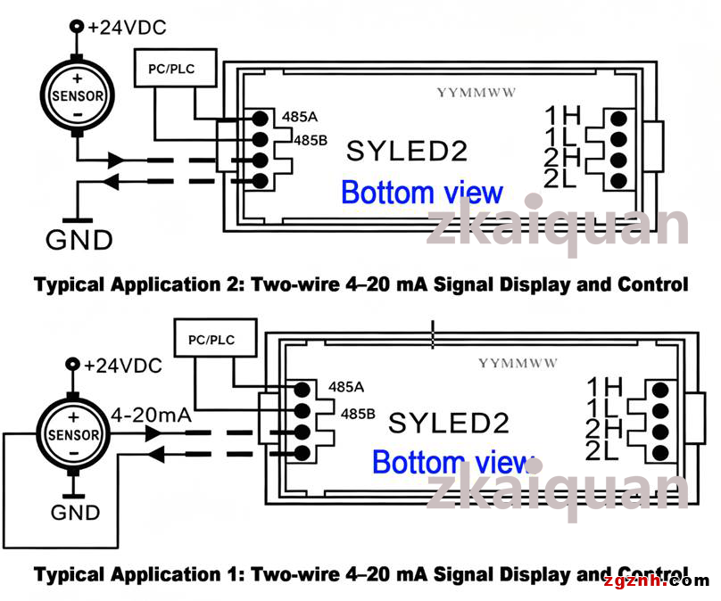
The SY LED2-485 is a low-cost, compact 2-wire passive intelligent LED digital display meter designed for 4–20mA current loops. It adopts a passive structure, with its input and output wires connected in series to the 4–20mA loop of transmitters. It linearly converts the 4–20mA analog signal in the loop into decimal digital readings according to user-defined measuring ranges. This product supports RS-485 communication; users may remotely connect PLCs or HMIs to read displayed values, as well as configure and modify parameters including module address, baud rate, alarm threshold and other settings.
The SY LED2 series digital display meter works on the 2-wire passive principle. The electrical signal flowing through the measuring loop serves simultaneously as the meter’s input signal and operating power supply. This 2-wire passive design eliminates the need for external auxiliary power, delivering simple wiring, compact size, high precision and low cost. Traditional analog display meters rely on potentiometer adjustment, which only supports limited adjustable parameters, lacks flexibility and is susceptible to temperature drift. In contrast, this digital meter is controlled by a central processing unit (CPU) and operated via two built-in keys. It allows configuration of multiple parameters such as zero point, full scale, decimal point position, alarm values and delay time, offering outstanding flexibility and practicality.
Equipped with an LED display panel driven by constant-current circuits for uniform brightness across the full 4–20mA range, the meter is integrated with reverse connection protection and overcurrent protection. It is applicable for monitoring physical quantities including temperature, pressure, flow rate and liquid level at control points in industrial sites, petrochemical plants, environmental monitoring stations and mining industries. In most application scenarios, sensors convert physical quantities such as temperature, pressure, flow and liquid level into 4–20mA electrical signals, which are then fed into the SY LED2 display meter for real-time numerical readout, facilitating comprehensive on-site control for operators.
The SY LED2-485 digital display meter measures DC 4–20mA current signals and draws power directly from the 4–20mA loop without an external power supply. Its displayed reading is not the raw measured current value, but a linear mapping value calculated between two preset reference points (4mA and 20mA).
Examples:
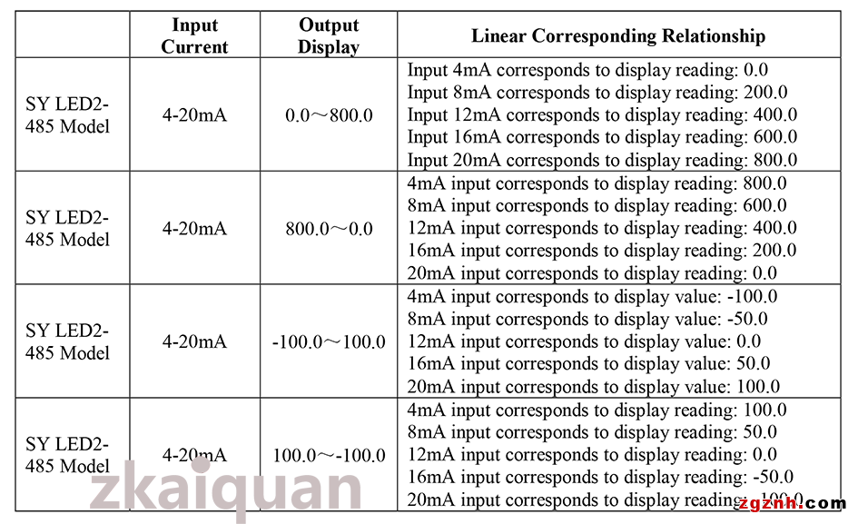
▲If 4mA is preset to 0 and 20mA is preset to 8000, the meter displays 2000 at an 8mA input and 4000 at a 12mA input.
▲If 4mA is preset to 1000 and 20mA is preset to -1000, the meter displays 0 at a 12mA input and -500 at a 16mA input. The display range of the meter spans from -1999 to 9999.
The SY LED2-485 is built with an alarm function and two isolated switching outputs to realize local display, on-site control and alarm triggering. The alarm function is pre-programmed; two PC452 optocoupler pads are reserved on the circuit board, and optocouplers can be installed later if alarm output is required. The meter provides two independent alarm points with configurable positive and negative alarm directions. Alarms are triggered based on display readings. When an alarm is activated, the decimal point on the last digit of the LED screen flashes, and alarm signals are output through dedicated ports to drive optocouplers.
The SY LED2-485 features a flame-retardant plastic housing and panel embedded installation structure.
Panel cutout dimension: 57.5×24.0 mm, tolerance +0.2 mm
It is widely used for digital indication of display control instruments and conversion signals inside cabinets.
Precautions:
▲ Do not reverse the polarity of the input current signal; otherwise, the digital display meter will be easily damaged.
▲ The normal input current shall not exceed 25 mA. once the input current reaches 100 mA, irreversible permanent damage to the meter will occur immediately. For testing and wiring into the current loop, it is recommended to connect a resistor of 200 Ω or above in series for circuit protection.
▲ Do not operate the device in humid environments or atmospheres with corrosive gas, which will shorten its service life or cause complete failure.
Technical Parameters of SY LED2-485 Digital Display Meter
▲ Operating Conditions
(1) Loop Current
Rated range: 3 ~ 22 mA
Absolute maximum limit: less than 100 mA
(2) Temperature Range
Normal operating range: -40℃ ~ +85℃
Extreme operating range: -45℃ ~ +125℃
(3) Relative Humidity: 20% ~ 90%RH
(4) Shock & Vibration: Complies with Group II environmental test standards for electronic instruments issued by the Ministry of Electronics Industry of China.
▲ Panel Display Mode
Black LED numeric digits and decimal points; digit height: 14.2 mm (0.56 inch).
▲ Display Setting Range
(1) Value corresponding to 4mA: -1999 ~ 9999
(2) Value corresponding to 20mA: -1999 ~ 9999
▲ Voltage Drop
Voltage drop ≤ 3.2 V, with overcurrent protection.
▲ Polarity Indication
A minus sign "-" will be displayed when the reading is below the zero point; no polarity symbol will be shown when the reading is above the zero point.
▲ Accuracy
Full-scale linear deviation: ±2 digits (based on the 2000 specification).
▲ Temperature Drift Error
≤50 PPM/℃
▲ Over-range Indication
Displays "oHH" for over-high range and "oLL" for over-low range.
▲ RS-485 Communication
Communication Interface: 1 channel standard RS-485 interface
Communication Protocol: MODBUS RTU protocol; compatible for network communication with mainstream-brand PLCs, RTUs and PC monitoring systems
Data Format: 10 bits (1 start bit, 8 data bits, 1 stop bit)
Address & Baud Rate: Address range 00H~FFH; optional baud rates: 1200, 2400, 4800, 9600, 19200 bps
Transmission Distance: Max. 1200 m via shielded twisted-pair cable
Anti-interference Performance: ±15KV ESD protection; communication response time <100 ms
▲ Dimensions
Overall dimension: 61.4 × 26.0 × 17.7 mm
Panel cutout dimension: 57.5 × 24.0 mm, tolerance +0.2 mm
Operating Instructions:
1. Installation
Install the meter with reference to the drawing: Product Photos, Outline Dimensions and Function Description of SY LED2-485 Digital Display Meter. The housing is made of ABS plastic. Push the meter into the opening on the cabinet panel, and fix the rear side with hot melt adhesive.
2. External Circuit Connection
(Refer to Product Photos, Outline Dimensions and Function Description of SY LED2-485 Digital Display Meter)
The SYLED2 digital display meter adopts a 2-wire passive operating mode, with only two external connecting wires: current input terminal and current output terminal. There are red and black leads on the back of the meter. The red lead is the current input terminal, and the black lead is the current output terminal.
Do not reverse the wiring, otherwise the internal circuit will be easily damaged.
3. Menu Setting Method
After the input signal is connected to the meter, the meter powers on and performs self-check, the startup logo interface 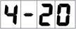 will be displayed, and then the meter enters the measurement display state automatically.
① Zero Setting (Set when the loop input current is 4mA)
Press A and B simultaneously to bring up the zero setting interface. Press A+B again to enter the zero setting page, where the current set value  is displayed, and the last digit is flashing. Press Key A to switch the flashing position among the four digital tubes
  ; the flashing digit is the adjustable position.
Press Key B to cycle the value of the flashing digit from 0 to 9. For the leftmost digit, it cycles among minus sign, -1, and numbers 0~9. Adjust each digit according to the target display value.
Note: The display range under 4mA input current is -1999 ~ 9999, with factory default value of 0.0.
After setting is completed, press A+B simultaneously to confirm the parameters and return to interface
② Full-Scale Calibration (Calibrate with 20mA loop input current)
Press Key A continuously to enter the full-scale setting interface . Press A and B simultaneously to access the full-scale parameter page, where the current preset value
 is displayed.
Note: The display range under 20mA input is -1999 ~ 9999, and the factory default value is 200.0.
The operation steps are identical to Section ①. After configuration, press A+B simultaneously to confirm settings and return to interface  .
.
③ Decimal Point Setting
Press Key A continuously to enter the decimal point setting interface . Press A+B to open the current parameter page
 . Each press on Key B shifts the decimal point one position to the left; repeated pressing will cycle the decimal point position leftwards. After adjustment, press A+B to confirm and return to interface
  .
.
④ Damping Time Setting
Press Key A continuously to enter the damping time setting interface . Press A+B to check the current setting value
  .
.
The adjustable damping time ranges from 0 second to 20 seconds.
Press Key A to decrease the value;
Press Key B to increase the value.
Values increase in increments of 0.5 seconds. once finished, press A+B to confirm and return to interface .
.
⑤ Alarm Switch Setting
Press Key A continuously to enter the alarm switch setting interface . Press A+B to access parameter configuration and view the current setting
 , which means all subsequent alarm parameters will be invalid. Press Key A or B to switch status to
  , which enables the alarm parameters below.
The flashing of the last digit indicates an active alarm trigger under any alarm condition. After setup, press A+B to confirm and return to the main menu. The factory default setting is  .
.
⑥ 1st Alarm Threshold Setting
Press Key A continuously to enter the 1st alarm threshold interface  . Press A+B to access the current threshold value page
 , with the last digit flashing.
Press Key A to switch the flashing position among the four digital tubes (the flashing digit is adjustable).
Press Key B to cycle the digit value from 0 to 9. The leftmost digit cycles among minus sign, -1, and numbers 0~9. Set the alarm threshold as required.
Note: The adjustable range of alarm threshold is -1999 ~ 9999.
After setting, press A+B to confirm and return to interface .
.
⑦ 2nd Alarm Threshold Setting
Press Key A continuously to enter the 2nd alarm threshold interface  . The configuration method is the same as Section ⑥. After setup, press A+B to confirm and return to the menu.
⑧ 1st Alarm Direction Setting
Press Key A continuously to enter the 1st alarm direction interface  . Press A+B to view the current setting
 , which stands for upward-crossing alarm: the alarm triggers when reading rises above the threshold.
Example: If the threshold is set to 1000, the meter alarms when the LED reading exceeds 1000, and stops alarming below 1000.
Press Key B to switch to status  , which stands for downward-crossing alarm: the alarm triggers when reading drops below the threshold.
Example: If the threshold is set to 1000, the meter alarms when the LED reading is lower than 1000, and stops alarming above 1000.
The alarm will be cleared automatically once the LED reading returns to normal value. After adjustment, press A+B to confirm and return to the menu.
⑨ 2nd Alarm Direction Setting
Press Key A continuously to enter the 2nd alarm direction interface . The adjustment steps are consistent with Section ⑧. After setup, press A+B to confirm and return to the menu.
⑩ Alarm Delay Time Setting
Press Key A continuously to enter the alarm delay setting interface  . Press A+B to check the current parameter
  .
.
Alarm delay time ranges from 0s to 30s.
Press Key A to increase the value;
Press Key B to decrease the value.
Values change in 1-second increments. After setting, press A+B to confirm and return to the menu.
Note: A value of 0 means no alarm delay. When delay is enabled, the alarm will not activate immediately after the alarm condition is met; the reading must stay within the alarm threshold continuously for the set delay time before alarming. The alarm will be cancelled instantly once the reading returns to normal range without delay.
Press Key A repeatedly to go back to the measurement display screen, and all parameter settings are completed.
4. 4mA & 20mA Calibration (Operate with caution)
Input a stable 4mA signal to the meter, hold down Key A until the display shows 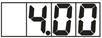 , then release the key. After 3 seconds, press Key A once again; the screen displays
 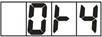 , meaning the current 4mA signal is saved as the standard calibration value.
Switch the input signal to 20mA, press Key A to trigger display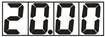 . After 3 seconds, press Key A again; the screen displays
 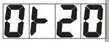 , meaning the current 20mA signal is saved as the standard calibration value.
Press Key A one more time to return to normal measurement mode.
Example of Product Parameter Setting & Selection:
An overrange indication will be triggered when the signal exceeds the maximum AD conversion range of the IC, or when the decimal-point-free reading is higher than 9999 or lower than -1999. English Translation (Industrial Instrument Manual Standard Version)
Case 1: Exceeding the IC maximum AD measurement range (calibrated for 4–20mA signal)
When 4mA corresponds to display value 0 and 20mA corresponds to display value 2000:
Display shows oLL for an input of 3.01mA; display shows oHH for an input of 26.01mA.
When 4mA corresponds to display value 2000 and 20mA corresponds to display value 0:
Display shows oLL for an input of 3.01mA; display shows oHH for an input of 26.01mA.
Case 2: Decimal-point-free readings exceed the range (-1999 ~ 9999)
When 4mA displays 0 and 20mA displays 9999: An input current of 20.01mA cannot be shifted without a decimal point, hence the meter displays oHH.
When 4mA displays -1999 and 20mA displays 5000: An input current of 3.99mA cannot be shifted without a decimal point, hence the meter displays oLL.
Alarm Output and Application:
▲The two channels of alarm signals are DC level signals generated inside the main CPU chip. They are output after optocoupler isolation. A low-level output indicates the alarm state, while a high-level output indicates the normal non-alarm state.
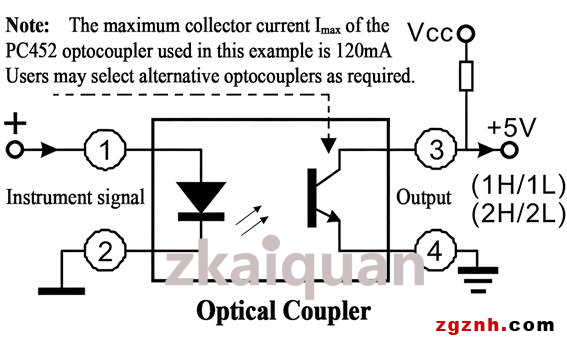
▲Since the display controller adopts passive two-wire operation with a minimum operating current of 3mA, the original alarm signal is weak, with a minimum current of only 0.5mA. A phototransistor-type optocoupler with strong current amplification capability is used for signal isolation, and the output mode is open collector (OC gate). After an external pull-up voltage is connected, the maximum output current can be expanded to 120mA.
The working principle of this phototransistor optocoupler is shown in the attached figure: Pins ① and ② serve as the input terminals of the optocoupler and connect to the alarm signal on the meter circuit board; Pins ③ and ④ are the isolated output terminals of the alarm signal, which are connected to the external power supply circuit of the meter for further amplification and current boosting. The processed signals can finally drive various actuators such as sound alarms, indicator lights, electrical equipment, refrigeration equipment, heating devices and motors.
▲The two isolated and current-amplified alarm signals are led out from four terminal holes marked "1H/1L" and "2H/2L" on the PCB at the rear of the meter.
• "1H/1L": 1st channel alarm output
• "2H/2L": 2nd channel alarm output
• Terminals 1H and 2H connect to the collectors of phototransistors;
• Terminals 1L and 2L connect to the emitters of phototransistors.
▲Limited by the maximum collector current (Ic) of the phototransistor, its current expansion and load driving capacity are restricted. If users require higher driving current to drive on-site devices such as relays, solenoid valves and stepping motors, an external power expansion circuit (power amplifier transistor or servo circuit) can be independently connected for current amplification, or customized products can be specially ordered.
RS485 Modbus RTU Mode:
The Modbus protocol defines the information structure that controllers can recognize and adopt. During communication over a Modbus network, the protocol enables each controller to identify its unique device address, recognize data addressed to itself, determine the type of operation to be executed, and extract data and information encapsulated in messages. Controllers can also assemble response messages and transmit them in accordance with the Modbus protocol.
Controller communication adopts master-slave architecture: only one device (the master device) is allowed to initiate transmissions (queries). All other devices (slave devices) generate corresponding responses based on data received from master queries.
Typical master devices: host computers, programmable meters.
Typical slave devices: programmable logic controllers (PLCs).
A master device can communicate with a single slave point-to-point, or broadcast messages to all slave devices simultaneously. For point-to-point communication, the targeted slave will return a reply message. No response will be generated for broadcast queries.
The Modbus protocol specifies a fixed frame structure for master queries, consisting of the device address (or broadcast address), function code, transmission data, and an error check field.
Slave response messages also follow the Modbus frame structure, which includes an acknowledgment field for confirmed operations, return data (if applicable), and an error check field. If a communication error occurs during message reception, or the slave fails to execute the received command, the slave will construct an exception message and send it as a reply to the master.
Two transmission modes are available for Modbus communication: ASCII and RTU. This display meter only supports the Modbus RTU mode.
In RTU communication mode, each 8-bit byte in a message carries two 4-bit hexadecimal characters, and Cyclic Redundancy Check (CRC) is adopted for error detection. Its advantage lies in higher data throughput compared with ASCII mode under the same baud rate.
Data Format:
The default baud rate is 9600 and it is configurable. The communication parameters are set as 8 data bits, 1 stop bit, and no parity check (NONE).
Communication Protocol
The serial port adopts the standard Modbus-RTU protocol, supporting Function Code 03 and Function Code 10.
Universal address (0XFF) and broadcast address (0X00) are available. The device address ranges from 1 to 254, with the factory default address set to 1. The maximum readable length of registers is 50 registers.
• Read Registers (Function Code 03)
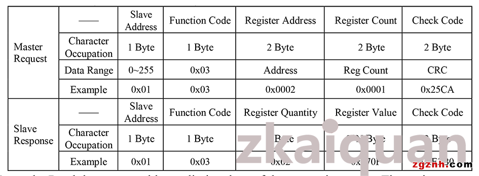
Example: Read the upper and lower limit values of the measuring range. The register address is 0x03, the register length is 2 (4 bytes in total), and both byte order and word order are big-endian.
Master Request (HEX): 01 03 00 03 00 02 34 0B
Slave Response (HEX): 01 03 04 FF 9C 03 E8 0A B7
The lower limit setting value of measuring range: 0xFF9C (-100)
The upper limit setting value of measuring range: 0x03E8 (1000)
Write Registers (Function Code 10):
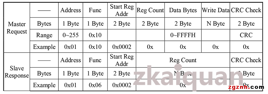
Example: Set the upper and lower limits of the measuring range. The starting register address is 0x03, the register length is 2 (occupying 4 bytes in total), and both byte order and word order adopt big-endian format.
The lower measuring range limit is set to -200;
The upper measuring range limit is set to 1500.
Master Request (HEX): 01 10 00 03 00 02 04 FF 38 05 DC 00 AA
Slave Response (HEX): 01 10 00 03 00 02 B1 C8
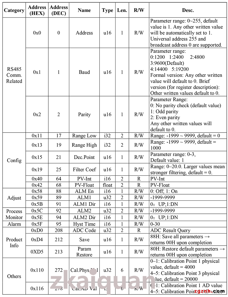
Register List for RTU Mode:
Special Notes:
▲All modified parameters take effect immediately. To permanently save settings, write 0x88 to the save register (Address 212). All modifications will be lost after power cycling without this saving operation.
▲Restore communication parameters to factory defaults
Power on the device while holding down Key B; communication parameters will be temporarily restored to default values. Original parameters will be restored after the next power cycle.
▲Restore all parameters to factory defaults
Method 1: Enter the DOT menu, press and hold Key A for 10 seconds. The device will exit the menu, restore all parameters to factory defaults and automatically save the configuration.
Method 2: Via communication: write 0x80 to register Address 213 to restore and save all default parameters. Read register 213; a value of 0x00 indicates the operation is finished successfully.
Overall Dimensions and Function Description:
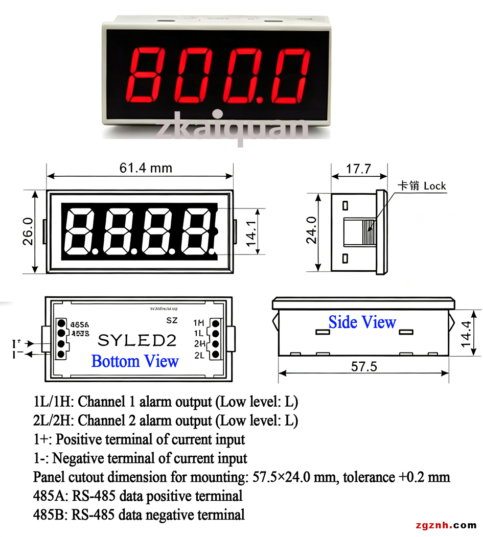
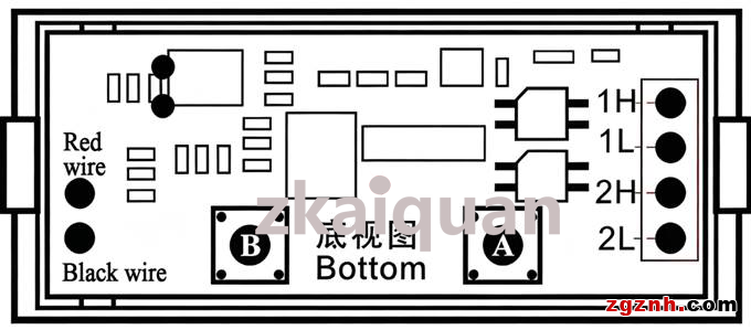
If users need to set parameters manually, carefully open the rear cover. The internal Key A and Key B are used for parameter configuration. Please set parameters strictly in accordance with the instruction manual. After setup is completed, carefully reinstall the rear cover back to its original position.
The internal schematic diagram of the digital display meter after opening is shown below:
Typical Application Diagram:
Guidelines for Model Selection & Ordering:
Please thoroughly read the entire manual before placing an order to confirm whether this product meets your application requirements and complete correct model selection.
▲Unless otherwise specified by customers, all products are calibrated at the factory to display "0.0" for 4mA input and "200.0" for 20mA input.
▲For first-time orders, customers are advised to specify display parameters; our company will complete calibration before delivery.
Shenzhen Zhikongquan Technology Co., Ltd.:Drawing on 28 years of profound industry experience and accumulated resources, we focus on sectors including industrial automation, sensors, industrial instruments, and robotics. We have integrated manufacturing resources from over a thousand manufacturers. We are committed to promoting Made in China and Created in China to the world, delivering high-quality, cost-effective Chinese products to manufacturing enterprises across the globe. only a selection of our products is listed on our catalog; feel free to contact us for more product information anytime.
Address: Room 1501, Global Logistics Center, No.1 Huanan Avenue, Pinghu Sub-district, Longgang District, Shenzhen City, Guangdong Province, P.R.China
Contact Person: Mulan.Liu
Title: Operations Director
Email: info@zgznh.com
sales1@zgznh.com
https://www.zgznh.com/mall/list-1505.html
WeChat: 13302910296
 粤公网安备44030702001206号