
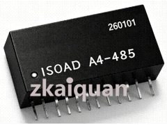



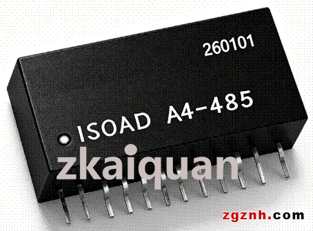
ISOAD A4-485:Two-Wire Passive Programmable Bus Communication Analog Isolation Acquisition IC
Two-Wire Isolated Programmable Analog Signal Data Acquisition Module
Prices in the link are for reference only. Contact the staff at the end of the article for exact pricing.
We accept OEM customization as well as ODM development, design and manufacturing services.
Product Features:
● PCB modular design, suitable for built-in installation inside transmitters and instruments
● No auxiliary power supply required; powered by two-wire signal loop, realizes loop current acquisition and transmission
● Supports RS485 communication; remotely connect to PLC/HMI for measured value reading and parameter configuration
● Low cost, compact size and high measurement accuracy; accuracy up to 0.1% FS at ambient temperature
● 3kV isolation between analog current loop input and RS485 bus output signals
● Embedded mounting design. Dimensions: 33.0 × 15.5 × 10.5 mm
● SIP 12Pin and DIN35 rail mounting options for flexible on-site installation
● Industrial operating temperature range: -40℃~+85℃ with high reliability
Typical Applications:
● Digital intelligent upgrade of traditional transmitters and instruments
● Retrofit & remote automation upgrade of industrial field control equipment
● MODBUS bus sensor signal acquisition and AD conversion
● Measurement, monitoring and remote control of power and gas equipment
● Monitoring of control points in petroleum, chemical, environmental protection and mining systems
● Multi-point centralized acquisition of temperature, pressure, flow and liquid level signals
● Fieldbus data collection for PLC and DCS systems
● Product development of instruments, medical equipment and industrial control devices
Overview:
ISOAD A4-485 is a low-cost, compact passive programmable bus communication intelligent isolated data acquisition module. Adopting a two-wire loop-powered design, it performs ADC conversion on the 4~20mA analog signals within the signal transmission loops of instruments, sensors and transmitters. After linear scaling according to the configured measuring range, the processed data can be acquired and read by host devices. The IC integrates reverse polarity and overcurrent protection. It is suitable for digital intelligent upgrading and retrofitting of various legacy traditional transmitters and instruments on industrial sites, and widely deployed for intelligent monitoring of control points for physical quantities such as temperature, pressure, flow and liquid level in petrochemical, environmental monitoring, mining and other industries.
At most industrial sites, various sensors convert physical quantities including temperature, pressure, flow rate and rotational speed into analog current signals. This data acquisition IC carries out isolated amplification and AD conversion for such signals, then transmits the data to control instruments, PLC/DCS, host computers and other equipment for remote measurement and control.
ISOAD A4-485 adopts two-wire loop-powered wiring, applicable to the isolated transmission and acquisition of standard 4~20mA analog signals between sensors, transmitters and PLC/DCS systems. No auxiliary power supply is required for module operation; the two wires can be directly connected in series to the on-site 4~20mA current loop. Multiple parameters including zero point, full scale, alarm output control and delay can be configured via software. The module adopts high-speed isolator technology to achieve 3000 VDC isolation between current loop signal input and RS485 bus, ensuring mutual immunity between sensors and host equipment for safe and reliable operation.
ISOAD A4-485 supports RS485 communication. It can be remotely connected to PLC/HMI to read measured values, and allows configuration and modification of relevant parameters such as module address, baud rate, measuring range and alarm threshold. The alarm status can be retrieved through registers.
The internal input signal has a linear correlation with the acquired reading. The maximum configurable measuring range value is 60000 and the minimum is -60000. For instance, for a 4~20mA input signal, the corresponding acquired readings range from 4000 to 20000: 4mA corresponds to 4000, 12mA corresponds to 12000, and 20mA corresponds to 20000.
Technical Specifications:
1. Operating Conditions:
● Input Signal: 4~20mA analog signal output from two-wire sensors or transmitters; minimum 3mA, maximum 40mA.
● Power Supply: Powered by 4~20mA current loop, no external power required.
● Temperature Range: Rated operating range: -20℃~+60℃
Extreme operating range: -40℃~+85℃
● Relative Humidity: 20%~90% RH
● Shock & Vibration: Complies with environmental test requirements for Group Ⅱ instruments per the Ministry of Electronics Industry standard.
2. Data Acquisition Method:
● Serial communication adopts standard Modbus-RTU protocol, supports function codes 03, 06, 10; equipped with standard RS485 interface.
3. Configurable Output Range: ±60000
4. Output data is negative when below the zero point value, and positive when above the zero point value.
5. Accuracy: 0.1% FS (at ambient temperature).
6. Temperature Drift Error: ≤50 PPM/℃
7. Isolation Voltage: 3000 VDC isolation between current loop input and RS485 bus.
8. Dimensions: 33.1 × 15.5 × 10.4 mm; Flame-retardant plastic housing with polyester encapsulation.
Notes:
1. Do not reverse the input signal (current direction); otherwise, the isolated data acquisition module may be damaged.
2. The input current signal shall generally not exceed 60 mA. Irreparable damage will occur to the isolated data acquisition module if the input current reaches 100 mA.
(It is recommended to connect a resistor of 200 Ω or more in series in the circuit for protection during testing or connection to the current loop.)
3. Do not use the device in humid environments or environments with corrosive gas; otherwise, its service life will be shortened or permanent damage may occur.
Dimensions and Pin Description:
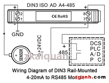
Typical Application Wiring Diagram for DIN3 Rail-Mounted Type:
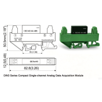
This 2-wire isolated analog signal data acquisition module is also available in a standard single-channel DIN3 rail-mounted version, enabling users to make direct field wiring conveniently. Thanks to its compact size and low cost, this model is not equipped with overvoltage, overcurrent and reverse polarity protection circuits at the signal input and communication output terminals. Users shall install protective devices according to on-site operating conditions.
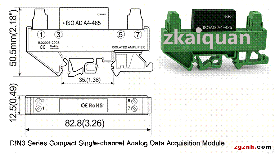
Outline Dimensions Drawing of DIN3 Rail-Mounted Type
Terms of Ordering & Model Selection:
● Please read the complete contents of this manual before placing an order to confirm whether this product meets your field application requirements and ensure correct model selection.
● It is recommended that you specify parameter requirements when ordering. The product can be calibrated before delivery for direct use on site.
Operation Instructions:
1. Installation
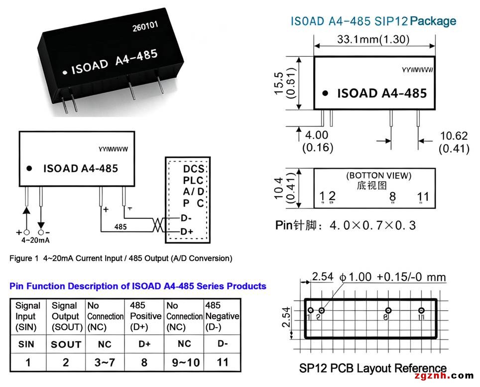
Refer to the Outline Dimensions and Pin Description for PCB layout and installation. The module adopts SIP12 (Single In-line 12-Pin) package. The DIN rail mounted version can be installed directly.
2. External Circuit Connection (Refer to Outline Dimensions and Pin Description)
This isolated data acquisition module operates in a **2-wire loop-powered** mode. Four external connection wires are required: two pins for analog current signal input and two pins for RS485 digital communication output.
Do not reverse the power connection; otherwise, internal circuits may be damaged.
3. Function Configuration Method
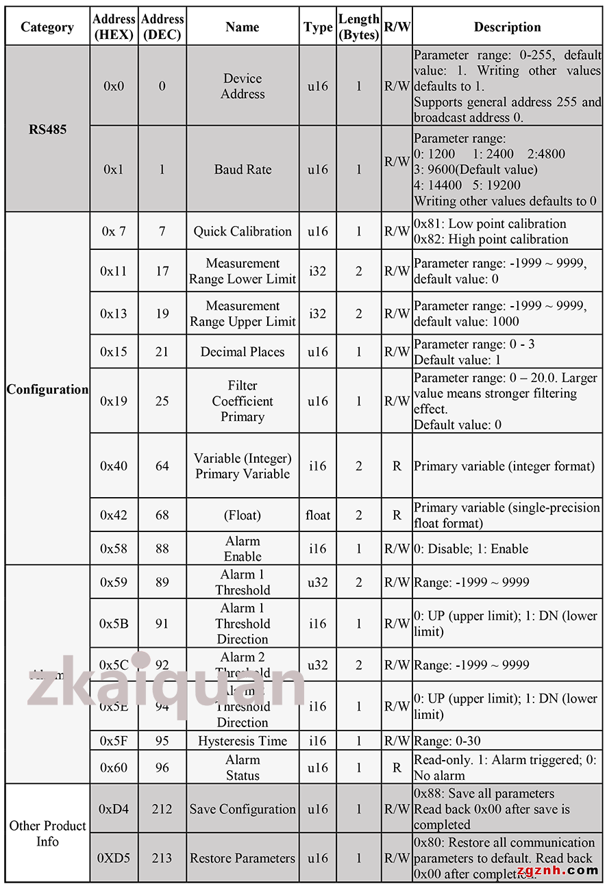
Parameters including communication address, baud rate, measurement range, alarm threshold and main variable can be configured by reading and writing corresponding registers.
Refer to the register table in the following section for details.
4. Alarm & Application
Upper and lower alarm thresholds as well as hysteresis time can be set via Register 88 ~ Register 95.
The alarm status can be queried in Register 96:
1 = Alarm triggered; 0 = No alarm.
Model Selection Example:
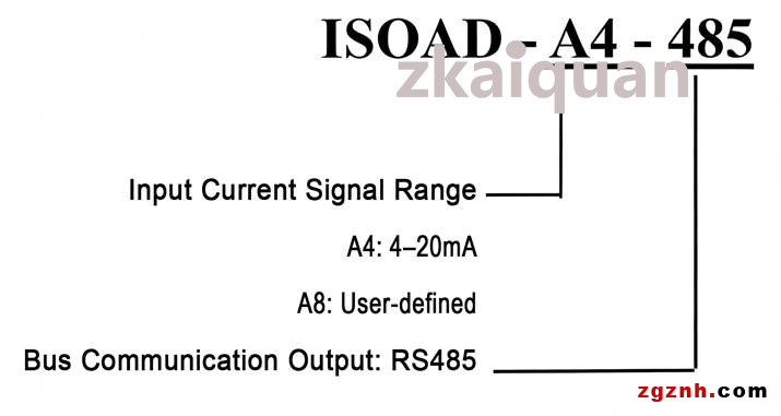
Model Selection Example 1:
Signal Input: 4–20mA
Model No.: ISOAD-A4-485
Model Selection Example 2:
Signal Input: 4–24mA
Model No.: ISOAD-A8-485
RS485 Modbus RTU Mode
The Modbus protocol defines the message structure that controllers can recognize and utilize. When communicating over a Modbus network, the protocol enables each controller to identify its own device address, recognize data addressed to it, determine the type of action to perform, and extract data and information contained in messages.
The controller can also compose response messages and transmit them via the Modbus protocol.
Controller communication adopts a master-slave mechanism: only one device (the master) can initiate transmissions (queries). All other devices (slaves) respond with corresponding data upon receiving queries from the master.
Typical master devices: host computers and programmable instruments. Typical slave devices: programmable logic controllers.
The master can communicate with a single slave individually, or broadcast messages to all slaves. For point-to-point communication, the slave returns a message as a response. No response will be generated for broadcast queries.
The Modbus protocol defines the format of master queries, consisting of the device (or broadcast) address, function code, all data to be transmitted, and an error check field.
Slave response messages are also structured in accordance with the Modbus protocol, including a field confirming the requested action, any data to be returned, and an error check field.If an error occurs during message reception, or the slave fails to execute the received command, the slave will construct an exception message and send it as a response.
There are two transmission modes for Modbus communication: ASCII and RTU. This module only supports Modbus RTU mode.
When communicating in RTU mode, each 8-bit byte within a message contains two 4-bit hexadecimal characters. CRC error detection is adopted. Its advantage is that more data can be transmitted compared with ASCII mode at the same baud rate.
Data Format:
The default baud rate is 9600 and can be modified. Data bit: 8 bits, Stop bit: 1 bit, Parity bit: NONE.
Communication Protocol:
Serial communication supports standard Modbus-RTU protocol, with function codes 03 / 06 / 10. It supports general address (0XFF) and broadcast address (0X00). Device address ranges from 1 to 254, default address is 1. The maximum length for register reading is 50.
⚫ Read Registers (Function Code 03):
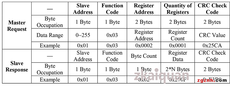
Example: Read the upper and lower limit setting values of the measurement range. The register address is 0x11, the register quantity is 4, occupying a total of 8 bytes. Both byte order and word order are big-endian.
Master Request (HEX): 01 03 00 11 00 04 14 0C
Slave Response (HEX): 01 03 08 00 00 01 90 00 00 07 D0 57 B7
Setting value of lower measurement range limit: 0x00000190 (400)
Setting value of upper measurement range limit: 0x000007D0 (2000)
⚫ Write Single Register (Function Code 06)
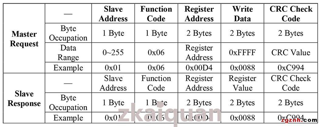
Example: Save configuration parameters. The register address is 0x00D4, register quantity is 1, occupying a total of 2 bytes. Both byte order and word order are big-endian.
Master Request (HEX): 01 06 00 D4 00 88 C9 94
Slave Response (HEX): 01 06 00 D4 00 88 C9 94
• Write Multiple Registers (Function Code 10):
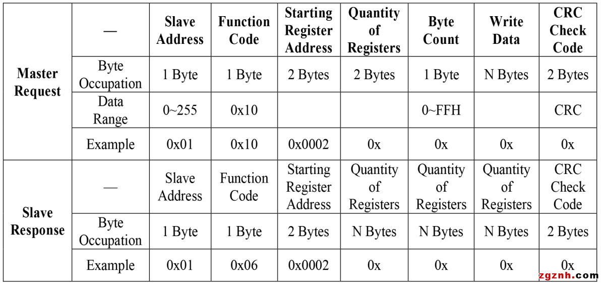
Example: Set the upper and lower limits of the measurement range. The starting register address is 0x03, the quantity of registers is 4, occupying a total of 8 bytes. Both byte order and word order are big-endian.
Lower measurement range limit setting value: 400
Upper measurement range limit setting value: 2000
Master Request (HEX): 01 10 00 11 00 04 08 00 00 01 90 00 00 07 D0 48 26
Slave Response (HEX): 01 10 00 11 00 04 91 CF
Special Notes for Software Configuration
1. All modified parameters take effect immediately. To permanently save the configurations, you must write the value 0x88 to the save register (Address 212). Otherwise, all settings will be lost after power cycle.
2. Restore default communication parameters
Write 0x80 to Address 213. This operation restores and saves the default communication parameters defined in Registers 0, 1 and 2. Read back Address 213; a value of 0x00 indicates the operation is completed.
This function is mainly used when the previously configured communication parameters are unknown and reconfiguration is required.
Register Table for RTU Mode:
 粤公网安备44030702001206号