
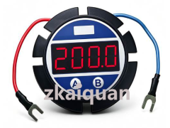



SY LED3:2-wire Passive Intelligent Loop (LED) Display Meter
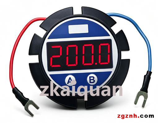
Embedded 2-wire Passive Programmable 4-20mA Loop (Four Digits LED) Display Meter
Prices in the link are for reference only. Contact the staff at the end of the article for exact pricing.
We accept OEM customization as well as ODM development, design and manufacturing services.
Features:
•Low cost modular design, easy to install in use.
•2-wire passive operation mode, no auxiliary power.
•High measuring accuracy, 4-digit display, ±2 digits.
•LED display panel, adapt to different lightness requirements.
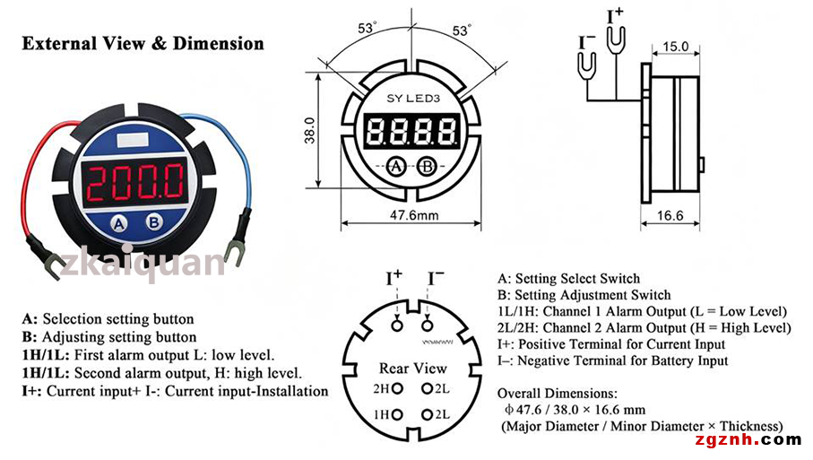
•Small size, dimension φ47.6/38.0×16.6mm (H.:16.6mm)
•Industrial operating temp.: -25℃ ~ 70℃, high reliability.
Applications:
•Sensor, transmitter operating status display.
•Industrial equipment monitoring or remote control
•Oil, chemical, environmental system monitoring.
•Temperature, pressure, flow, level signal monitoring and display.
•PLC, DCS system operation data acquisition and display.
•Developing meters & instruments, medical devices, industrial equipment.
Introduction:
SY LED3 4-Digit 2-wire Passive Intelligent 4-20mA Current LED Display Meter input is passive signal, output 2 lines can be connected to the transmitter 4-20mA loop in serial. It can display decimal number correspondingly based on the settings through 4-20mA analog signal in the loop. SY LED3 series Display Meter is designed on the base of 2-wire passive mode; it measures the electric signal which can be used as the input signal and the operating power supply of the display meter. The meter operates without power supply, low cost, high precision, small size, so it is very convenience to use. The traditional analog display meter uses potentiometer to do adjust parameters, it is not convenience and very easy to be effected by temperatures. Compared with traditional analog display meter, the LED display meter is set by 2 buttons and controlled by CPU, the zero, span, decimal, alarm, delay time, etc parameters can be set by users, it is much more flexible and convenient in use. That display meter has use LED display board and operates in continuous voltage, in the 4-20mA measuring range, the display digits are in equal and stable brightness. It has anti-reverse connection, over-current protection and is widely applied in industrial site, oil, environment monitor, temperature, pressure, flow, level measuring, etc site and fields. In the actual applications, the LED display meter converts temperature, pressure, flow, level, etc physical quantity into 4-20ma signal, then connect with SY LED3 display meter, it displays the temperature, pressure, flow, level, etc physical quantity to provide convenience for user to monitor and control the industrial site.
SYLED3 Display Meter is used to measure 4-20mA DC current signal, it does not need power supply and get power from 4-20ma current loop. The digits displayed are not the actual current value, it is the preset value of 4mA, 20mA, and displays the current valued measured based on the preset value in linearity method. E.g.: 4mA is set to 0, 20mA is set to 8000, then if input is 8mA, the meter displays 2000, input is 12mA, the meter displays 4000. If 4mA is set to 1000, 20mA is set to -1000, when input is 12mA, the meter displays 0, input is 16mA, the meter displays -500. The max. display range is 9999, that is four digits, min. Display range is -1999. SY LED3 Digit Display Meter has alarm function and 2-channel isolated switch quantity output to realize timely display, controlling and alarm. The alarm function is realized by programming, and there are 2 pieces of PC452 land pad is reserved for customer use when alarm function is required. The display meter has 2 alarm points which can be set in up and down directions. The alarm target of the alarm point is the digit displayed, when there is alarm, the last decimal of the LED Meter is flashing, and the alarm signal is output through terminal which can drive the Optocoupler.
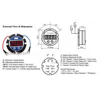
SY LED3 Dimension: Ф47.6/38.0×16.6mm, Height:16.6mm, the external shell is made of flame-retardant plastic. The meter is mainly used to display the sensors or transmitter or controlling meters signals.
The display meter panel perforation dimension: 33x20.5 +0.2mm
Note:
● Do not connect input signal (current polarity) in reverse, otherwise it may damage the display meter.
● Input current signal usually should be no more than 25mA, if input is up to 100mA, there is irreparable damages. In testing it with the current loop, 200Ω or larger resistance should be added in series in the loop to protect the display meters.
● Do not use it in humid and corrosive environment, otherwise it will reduce the life-span or cause irreparable damage.
SY LED3 Display Meter Technical Parameters:
1. Using conditions
(1)Current: Rated range 3~22mA
Limited range: less than 100 mA
(2) Temperature range: Rated range: -20℃~60℃
Limited range: -40℃~70℃
(3) Relative humidity 20%~90%RH
(4) Shock & Vibration: meet industrial electronics environmental test II meters’ requirements.
2. Panel display method:
Black LED digits and decimal display, digits height 10.1mm (0.40inch)
3. Four-digit Display Meter Setting Range:
(1) 4mA:-1999~9999
(2) 20mA: -1999~9999
4. Voltage drop: Voltage drop ≤3.2V, with over-current protection.
5. Polarity conversion: If lower than the zero limit, the meter display “-”, if higher than the zero limit, no polarity mark display.
6. Accuracy: linearity offset ±2 digits (to 2000 rated value).
7. Temperature error:≤50PPM/℃
8. Over-range display: “oHH” or “oLL”.
9. External Dimension: 35x22.5x17.5mm Flame retardant housing shell.
10. Panel perforation dimension: 33x20.5 +0.2mm
External View & Dimension:
Operation Instruction:
Installation
Refer to the dimension of the LED display meter; the external shell is ABS plastic. Push the Display Meter into the rail of cabinet, and fixed it by hot melt adhesive.
External circuit connection
SY LED1 Display Meter operates in 2-wire model, only 2 wire kept for user: current input terminal and current output terminal. There are 2 wires: black and red. The red wire is current input terminal, the black wire is current output terminal. Do not do reverse connection.
1. Menu setting.
If want to reset the parameters, user has to open the back cover. The internal structures shown as follow. Button A and B are used to set parameters, please refer to instructions below and set it accordingly.
Input signal to the meter, the meter is in power-on self-test state and displays the mark 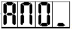 , then turn into the measuring display state.
● ①Zero setting (when it is 4-20mA current loop input )
Press button A+B, it shows the zero setting interface 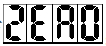 , then press A+B again, turn into zero setting, the interface shows the current setting value
 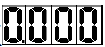 , at this time the last digit is flickering, press button A, four digital tube are flickering alternately, flickering digit is the bit to be adjusted, press button B, the digit of flashing bit changes from 0 to 9 in turn. The first digit of left side changes from the "–; -1; 0 to 9 in turn)," users set them according to the values displayed (Note: 4mA display value range of 4mA is: -1999 ~9999, the default value is "0.0"). Complete the setup, press button A+B to confirm and return the interface
  .
.
②Full scale/Span setting (when it is 4-20mA current loop input )
Continue to press button A to go to span setting interface 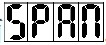 , then press button A + B, turn into span settings, the interface shows the current setting value
 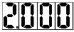 . (Note: For 20mA, the display range is from -1999 to 9999, the default value "200.0"). The rest of the operation is the same as that in ①. Complete the setup, press button A+B to confirm and return the interface
 .
.
③Decimal point setting
Continue to press button A to go to the decimal point setting interface 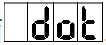 , then press button A + B, turn into current value setting interface
 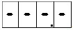 , press button B, the decimal point is shifted one bit to the left
 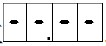 . Press button B in continuous, the decimal point shifts to the left in turn. Complete the setup, press button A+B to confirm and return the interface
 .
.
④ Damping time setting
 Continue to press button A to go to damping time setting interface
  , then press button A + B,go to the current value setting interface
  , the damping time range can be set from 0 seconds to 20 seconds, press button A, the time value is down ↓, press button B, the time value is up ↑, the setting value changes based on 0.5s multiplied. Complete the setup, press button A+B to confirm and return the interface
  .
.
⑤ Alarm switch setting
Continue to press button A to go to the alarm switch settings interface , then press button A +B, go to the alarm switch setting, the meter displays the current setting value
  , indicating the following alarm settings do not come into effect. Press button A or B to switched it into
  , indicating the following alarm parameters come into effect. All the alarming indicates through the last flashing point. Complete the setting, press button A + B to confirm and return to the menu. The factory default setting is
  .
.
⑥ The first alarm point setting
Continue to press button A to go to the first alarm setting interface  , then press button A + B, go to the first alarm current value setting
  , the first digit in the left is flickering, press button A, two digital tubes are flickering alternately, flickering bit is the bit to be adjusted. Press button B, the flickering digits change from 0 to 9 in turn, set the limit or boundary point based on the value displayed. (Note: The alarm setting value represents the percentage of the current signal input, such as the setting is
  , means that alarm limit point is (20mA-4mA) * 50% +4 mA = 12mA, when the input current is greater or less than 12mA (it’s up to alarm direction setting), the micro-controller outputs alarm signal to drive the optical-coupler, then it gives an alarm through external alarm equipments connected to the meters (the alarm function is designed according to users’ requirements). Complete the setting, press button A + B to confirm and return to the main menu.
⑦ The second alarm point setting
Continue to press button A to go to the second alarm point setting interface  , the setting method is the same as that in ⑥. Complete the setup, press A+B to confirm and return to main menu.
⑧ The first alarm point direction setting
Continue to press button A to go to the first alarm point direction setting interface  , then press button A + B, go to the current value setting interface
  , indicating it gives an alarm when the value varies from low to high, e.g., set the limit point to 12mA, it give an alarm when the input current is increased from 4mA to the value which is higher than 12mA, no alarm when the current is decreased from 20mA to the value which is lower than 12mA. Press button B, shift to
 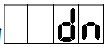 , indicating it gives an alarm when the value varies from high to low, e.g., set the limit point to 12mA, no alarm when the current is increased from 4mA to the value which is higher than 12mA, it gives an alarm when the input current is decreased from 20mA to the value which is lower than 12mA. When the input current is restored to the previous current value (before the state of alarm), the state of alarm is canceled. Complete the setup, press A + B button to confirm and return to the main menu. (Note: In the state of alarm, the last decimal point in the LED display panel is flashing which indicates the current state is in alarm conditions. )
⑨ The second alarm point direction setting
Continue to press button A to go to the second alarm point direction setting interface  , the setting method is the same as that in ⑧. Complete the setup, press A+B button to confirm and return to menu.
⑩ Alarm delay time setting
Continue to press button A to go to alarm delay time setting interface  , press button A+B to go to current value setting interface
  ; the alarm delay time can be set to the value from 0 seconds to 30 seconds, press button A, the time value is up ↑, press button B, the time value is down ↓, the setting value changes based on 1.0s multiplied. Complete the setup, press button A+B to confirm and return the interface. (Note: 0 means no delay, it will not give the alarm immediately when it meets the alarm condition, but go to the alarm state after the value displayed meets the alarm condition for several seconds, when the value restored to that in normal sate(no alarm), state of alarm is released without delay. Continue to press button A to return to the measuring display interface, the end of all settings.
5 . 4mA and 20mA Calibration (that settings should be done cautiously)
Input 4mA signal to the meter, press and hold the A button until the digital meter displays 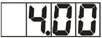 . Stop to press button for 3Seconds, then press button A again, the meter shows
 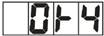 , now the 4mA current input signal sampling has been saved as the standard. Change the nput signal into 20mA, press button A, the meter displays
 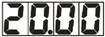 , press button A after 3Seconds, the meter displays
 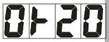 . 20mA current input signal sampling has been saved as the standard. Press button A again, return to the state of measurement.
Model selection examples:
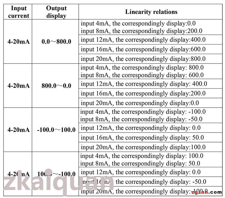
When the signals measured is beyond the limits of AD bit of the IC measuring range, or the display value is greater than 9999 or less than -1999 without decimal points, do the over-range display.
Beyond the measuring limit AD bit of the IC (4-20mA calibration)
4mA : display 0, 20mA: display 2000, input 3.01mA, display oLL, input 26.01mA, display oHH.
4mA : display 2000, 20mA: display 0, input 3.01mA, display oLL, input 26.01mA, display oHH.
The digit displayed is greater than 9999, less than -1999 without decimal point:
4mA: display 0, 20mA: display 9999, 20.01mA : display oHH, because the input has no decimal point, it can be shifted.
4mA: display -1999, 20mA: display 5000, 3.99mA: display oLL, because the input has no decimal point, it can be shifted.
Alarm Output and Applications:
1. In main CPU chip, there is DC current level signal output which generates from two-channel alarm signal, the low level output indicates the alarm state, high level output indicates non-alarm state.
2. The display digital meter operates in 2-wire passive mode, the min. operating current is 3mA, so the alarm signal is also very weak, the min. current is 0.5mA. The meter isolates the signal through photosenstive triode type optical-coupler, and adopts open-collectoer (OC) output. The output is connected to pull-in voltage, the current can be amplified to 120mA. The functional block of photosenstive triode type optical-coupler below: in the diagram, the signal from meter is isolated by optical-coupler. ①② is the input terminal of optical-coupler, connect to the alarm signal of the meter, “③④”wiring terminals are the output terminals of open-collector of optical-coupler, the terminals are to be connected to external power supply circuits of the meter to do further amplification and strengthen on alarm signal, and to drive the required components like sound, light, power, cool, heat, motor, etc.
3. Two-channel alarm output, “1H /1L”: the first alarm output, “2L /2H”: the second alarm output, “1H”, “2H”: connect to photsensitive triode collector, “1L”, “2L”: connect to emitter.
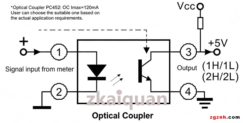
3. Due to the max. current limit of photosensitive triode IC, the capability of the meter in current amplification and drive load is limited. If the greater drive current is required to propel inverters, magnetic valves, stepper motor or other devices, user can add power expansion circuit (power amplifier tube or servo circuit) to amplify current or order it from us specially.
Ordering Notes
Please read the data sheet carefully before placing orders to ensure that products to be ordered can meet the requirements in real applications and there is no mistakes in model selection.
1. The default values: 4mA : display"0.0", 20 mA: display "200.0"
2. Any special requirements on display specifications, please notify us. The meter will be calibrated according to user’s requirements before ex-factory.
3. User should notify us the signal input type and the value of parameters below: AC, DC, reisitance (displacement or potentiometer), electric-bridge (pressure or weighing).
Note: The specification is subject to change without notice. For details, contact sy@sun-yuan.com.
Shenzhen Zhikongquan Technology Co., Ltd.:Drawing on 28 years of profound industry experience and accumulated resources, we focus on sectors including industrial automation, sensors, industrial instruments, and robotics. We have integrated manufacturing resources from over a thousand manufacturers. We are committed to promoting Made in China and Created in China to the world, delivering high-quality, cost-effective Chinese products to manufacturing enterprises across the globe. only a selection of our products is listed on our catalog; feel free to contact us for more product information anytime.
Address: Room 1501, Global Logistics Center, No.1 Huanan Avenue, Pinghu Sub-district, Longgang District, Shenzhen City, Guangdong Province, P.R.China
Contact Person: Mulan.Liu
Title: Operations Director
Email: info@zgznh.com
sales1@zgznh.com
https://www.zgznh.com/mall/list-1505.html
WeChat: 13302910296
 粤公网安备44030702001206号